Link Trainer Project..


Re: Link Trainer Project..
G-CPTN technical problems continued at viewtopic.php?f=29&t=1659&start=40#p349719
Re: Link Trainer Project..
'Splain please.
Been in data comm since we formed the bits individually with a Morse key.
Link Trainer Project..
I am still playing with my Link Trainer project.....
The glass instrument panel is slowly coming together.
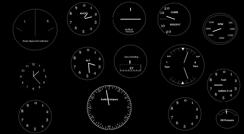
I am trying to keep this in WWII era but I have made a few assumptions that might benefit from scrutiny. The 'beam approach indicator' is a crossed needle instrument and I have only a vague notion as to what the ground end might have been, whatever, I am considering feeding this from ILS. The ILS of course will come from MS FS via FSUIPC and the same for the other instruments too.
The term 'radio compass' seems to have been loosely applied to various radio direction finding systems but this one has a fixed card and so indicates radio source relative to aircraft.
There is a problem with doing this project with the asthmatic PC and these simple graphics in that it is difficult to rotate a graphic image so the radio compass card is static and the gyro heading is the rolling ribbon (or drum) type.
There is room still for a couple of more 'clocks'!
The glass instrument panel is slowly coming together.
I am trying to keep this in WWII era but I have made a few assumptions that might benefit from scrutiny. The 'beam approach indicator' is a crossed needle instrument and I have only a vague notion as to what the ground end might have been, whatever, I am considering feeding this from ILS. The ILS of course will come from MS FS via FSUIPC and the same for the other instruments too.
The term 'radio compass' seems to have been loosely applied to various radio direction finding systems but this one has a fixed card and so indicates radio source relative to aircraft.
There is a problem with doing this project with the asthmatic PC and these simple graphics in that it is difficult to rotate a graphic image so the radio compass card is static and the gyro heading is the rolling ribbon (or drum) type.
There is room still for a couple of more 'clocks'!
Been in data comm since we formed the bits individually with a Morse key.
-
Fox3WheresMyBanana

- Chief Pilot

- Posts: 13249
- Joined: Thu Sep 03, 2015 9:51 pm
- Location: Great White North
- Gender:
- Age: 61
Re: Link Trainer Project..
This any use?
See the photos, as there's quite a bit of relevant detail
https://www.historicflyingclothing.com/ ... prod_19540
See the photos, as there's quite a bit of relevant detail
https://www.historicflyingclothing.com/ ... prod_19540
Re: Link Trainer Project..
Thanks, I have quite a collection of similar documents but not that particular one. I modelled the centrally grouped instruments on the RAF Blind Flying Panel. We have a quite a few of these instruments in our museum but I am not about to start messing around with 80 year old instruments with various radioactive paints slowly turning to dust in their innards.
I have only a vague description of how the crossed needle approach instrument operated but I do know they must have been popular enough judging by the number on junque shop shelves around here. Perhaps if I drive it with ILS inputs nobody will know the difference!
The genuine Link Trainer we have in captivity has the Blind Approach Indicator as shown opposite page numbered 10 of your document. It has two needle-type indicators and two rather clunky looking neon lamp holders. As we had them here they must have been used to train pilots of the Empire Training Scheme, however it is interesting that one of my RAF booklets says the glide slope portion was not implemented (maybe a clever idea that did not pan out in practice) but obviously they went ahead and made thousands of the instruments.
Bearing in mind the constraints of resources I have on hand I have decided to do something that will be functional and readily representative. If museum visitors want to study a genuine panel that can walk across to another hangar and feast their eyes, but they will not be able to 'fly' that one.
Been in data comm since we formed the bits individually with a Morse key.
Re: Link Trainer Project..
John - is the aim to enable basic radio navigation exercises or to enable a runway approach? Using a pseudo ILS input will satisfy both but limit the navigation part of the exercise to flying between airports with an 'ILS' in your database and depending on how you are to simulate the 'localiser' input from the PC (how are you doing that?) might limit you to flying only on a particular QDM to an 'ILS' airfield for the 'navigation' exercise.
Understanding how you are to implement the 'position' function of the system in the programme would help and I do not understand the need to 'rotate' the image?
Understanding how you are to implement the 'position' function of the system in the programme would help and I do not understand the need to 'rotate' the image?
Re: Link Trainer Project..
The aim is basic navigation exercises but a runway approach as far as practicable. There are no wheels on any Link Trainer that I have heard of.
An example of a navigation exercise would be to find and fly a Radio Range and maybe leave one and get onto another, somewhat like the North American 20-30's area all weather navigation. The Radio Range that we had close to here had procedures to cross the cone of silence at 800' then a 2.5 degree turn to bring you to the end of the runway. That is one exercise I have in mind.
I thought I had written a little story on this site that involved an imaginary flight in a Proctor from Chatham Island to Christchurch with a night time landing, in a Link Trainer.
The pseudo ILS idea came about because our genuine Link Trainer has Blind Approach Indicator. That may have been for the same system as for the indicator in the book that Fox3 showed us. That indicator instrument is too complex for my simple graphics but I know there was another type of 'Blind Approach Indicator' that saw service in WWII which comprised two crossed needles so I have drawn one of that type. I do not know how the two needle one works or if it was just centerline indication or if glide slope was somehow represented.
Strictly speaking, I am only interested in ILS because I will have ILS data and I can get that from MS Flight Simulator that will be running in my machine. I am using MS FS as a convenient way of creating a virtual aircraft model with pilot inputs and realistic data outputs. I do not want MS FS scenery display in the Link Trainer although there might be one at the instructor's position.
The only images we are talking about are the cockpit instrument panel and for that I have a minimal static graphic background display on to which I can draw the instrument needles. Some instruments such as ADF (some?) have a rotatable compass card and to simulate that I would need to rotate a card graphic. Simple Windows graphics suddenly get much more difficult, slower and a general pain in the butt when rotating images are introduced to the mix. So if you want to try an NDB let down in my Link Trainer you will have to cope with the old style radio compass.
The Radio Range is easy for me as it will be totally aural and I just have to define a location and the orientation of the four beams in an 'ini' file and MS FS does the rest. These systems were on LF and MF and so usable for a few hundred miles and so long as you could hear one beam you could find your way to the transmitter station and it's 'cone of silence'. These stations were usually in the vicinity of an airfield, the one at Christchurch NZ was about 2.5nm from the airfield and on the extended runway centerline.
I am sorry if this account is a little confusing but if you only knew the muddle that is churning around in my brain!
John
Been in data comm since we formed the bits individually with a Morse key.
Re: Link Trainer Project..
You might find this of interest, John - a bit of 'ILS history'. https://www.centennialofflight.net/essa ... /POL14.htm. The two ADF displays you are talking about are the RBI (fixed numbers and wot you have on your panel) and the RMI which needs a/c heading input and yes, a rotating card display. Years ago I wrote a simple RMI training programme with (rotating) graphic on my Sinclair spectrum - in BASIC, of course - with a fair bit of graphics flicker and not too speedy, but more than adequate for Rate1 turns. I would suggest sticking with the RBI on which countless hordes of pilots (including me) have trained. Harder work than an RMI but quite doable. I would recommend sticking with the Radio Range exercise if you feel you can feed the data into MsFS. An ILS, in particular the GP data, would be a considerably harder data file to create, and will significantly increase "the muddle that is churning around in your brain"! 
You did indeed post your 'Proctor' story which you should be able to find with 'search'.
You did indeed post your 'Proctor' story which you should be able to find with 'search'.
Re: Link Trainer Project..
Thanks for that interesting page.
So the RBI it is then. I have so far managed to almost totally avoid any flickering and I would like to keep it that way!
I rather like the Radio Range as it will be an almost total novelty to most users and it has a place in local history. In fact it was possible to fly from Gander NF to Christchurch NZ guided by ears alone! Christchurch was then, as it is now, somewhat the end of the world and just a Proctor ride away you could fly to the antipode of London!
MsFS can be readily interfaced to by various available add-ons and I use FSUIPC. The way it works is FS has a generous table of data items which it will share with other applications, some items can only be read and others can read and written to. I will be reading Lat/Long and driving a pen plotter to take the place of the Link Trainer's table to turtle gadget.
I had considered using the same position information to drive my Radio Range Morse course signals but I have since found a site that provides an add-on which seem to work quite nicely, the site is MSFS Astro Navigators Lounge, this is a Discord channel and is over polluted by all manner of kiddie icons, greebles and other infuriating visual feebleness. But there is good stuff to be had there if you are interested in flight simulators and the old ways of finding your way around the world with simple instruments and brain power.
Been in data comm since we formed the bits individually with a Morse key.